
Fire safety alarms are crucial in both residential and industrial environments. Early fire detection can prevent significant damage and save lives. Flame sensors offer one of the most efficient methods of fire detection. Here we outline how to construct a simple and reliable Flame-Sensing Fire Alarm System using an Arduino Nano board.
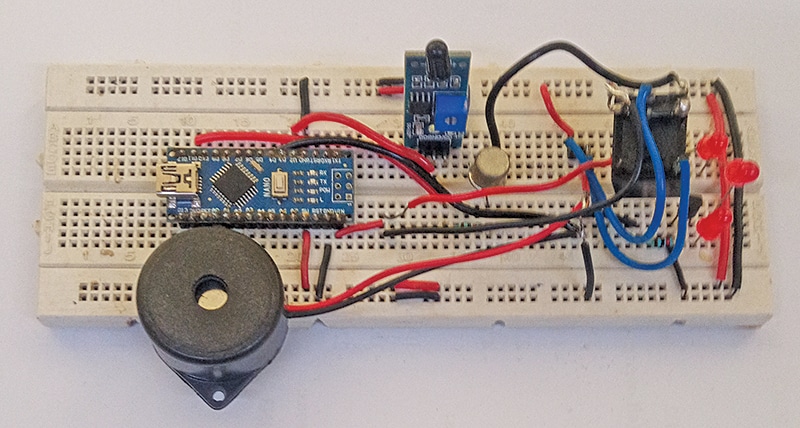
This fire alarm is intended for hobbyists and individuals interested in learning the basics of electronic sensors and alarms. The simplicity of this device can pave the way for creating life-saving systems. Fig. 1 shows the author’s prototype on a breadboard.
| Parts List |
| Semiconductors: IC1 – LM7812, 12V voltage regulator T1 – BC548 NPN transistor T2 – SL100 NPN transistor BR1 – 1A bridge rectifier LED1-LED3 – 5mm red LED D1 – 1N4007 rectifier diode Resistors (all 1/4-watt, ±5% carbon): R1-R3 – 1-kilo-ohm Capacitors: C1 – 1000μF, 35V electrolytic C2 – 100nF ceramic disk Miscellaneous: Hooter – 230V AC operated RL1 – 12V SPDT relay CON1-CON3 – 2-pin connectors Sensor1 – Flame sensor module X1 – 230V AC primary to 15V, 500mA secondary transformer |
Arduino based Fire Alarm – Circuit and Working
Fig. 2 presents the circuit diagram for the fire alarm using a flame sensor and Arduino Nano. The system is powered by a step-down transformer (X1), a bridge rectifier (BR1), a 12V voltage regulator (LM7812), and a flame sensor module connected via CON2. It includes a 12V SPDT relay (RL1), three LEDs (LED1 through LED3), and two transistors (BC548 and SL100), along with some other components.
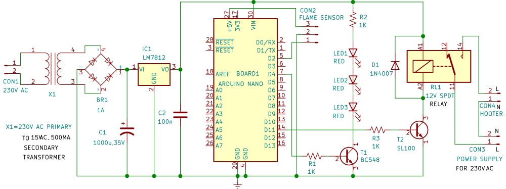
The circuit operates on 12V DC, which is derived from the 15V, 500mA secondary output of transformer X1. The 230V AC mains supply connects to the primary of X1 through connector CON1. On the secondary side, the 15V AC is rectified by BR1, filtered by capacitor C1, and regulated to 12V via IC LM7812 to power the circuit.
The flame sensor module, the core of the circuit, has three pins: Vcc, GND, and output (D0). These are connected to the 5V, GND, and D2 pins of the Arduino Nano, respectively.
The flame sensor detects fire or other light sources within a wavelength range of 760nm to 1100nm, making it essential for safety applications. The sensor uses the YG1006, a high-speed, highly sensitive NPN silicon phototransistor, to detect flames.
Three red LEDs (LED1 through LED3) provide visual indication, driven by transistor T1. T1’s base is connected to pin D4 of the Arduino Nano via resistor R1. Audio indication is provided by a 230V AC hooter, which is controlled by a 12V SPDT relay. Transistor T2 drives the relay, with its base connected to D11 pin of the Arduino Nano via resistor R3. The hooter connects to the normally-open (NO) contacts of the relay.
When the flame sensor detects a flame, it triggers two actions: the three LEDs light up for visual indication, and the hooter sounds for audio alert.
Arduino Code for Flame-Sensing Fire Alarm System
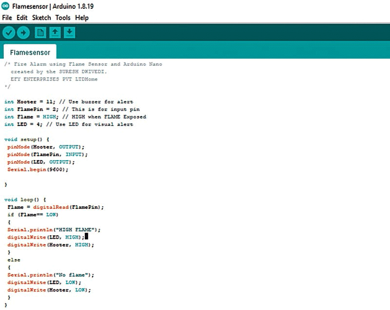
The source code for the project is written in the Arduino IDE platform. Before uploading the sketch to the Arduino Nano board, ensure the correct board and port are selected. Once confirmed, upload the sketch Flamesensor.ino to the board. Fig. 3 shows a screenshot of the source code.
PCB Design and Layout
An actual-size, single-sided PCB layout for the fire alarm is shown in Fig. 4, along with its component layout in Fig. 5.


Construction and Testing
After assembling the circuit on the PCB, it should be enclosed in a suitable box. The LEDs (LED1 through LED3) and CON2 should be fixed at the front of the box. The flame sensor should be connected across CON2 and positioned to ensure easy detection of flames.
Once the circuit is assembled, install the unit in an appropriate location where the flame sensor can effectively detect fire. To test the device, upload the source code to the Arduino Nano using the Arduino IDE. Afterward, disconnect the Nano board from the laptop or desktop, and connect 12V to the circuit.
Bring a small flame (such as a lighter) near the flame sensor. The buzzer should sound, and the LEDs should light up, signalling flame detection. Once the flame is removed, the buzzer and LEDs should deactivate, confirming no flame is detected. The flame sensor is now operational and can be installed at a location as needed.
Bonus: Watch the step-by-step video tutorial of this DIY project.
Also Check: Other interesting DIY Arduino Projects
S.C. Dwivedi is an electronics enthusiast and circuit designer at EFY


