
This is the second part of designing the world’s smallest phone Indus Phone, where the UI is integrated with the basic functions of the phone. Previously, the Indusphone user interface (UI) was designed and the GSM module was tested, integrating it with the IndusBoard coin to advance the design. This segment combines the UI with such functions as contacts and calculator. The connections established in part 1, published in EFY’s October issue, remain unchanged. The focus now shifts to software and UI integration for the IndusBoard phone.
The initial step involves integrating fundamental functions like dialling a number, making calls, checking call status, handling incoming calls, and displaying the idle screen within the previously designed UI. Fig. 1 illustrates the IndusBoard phone.
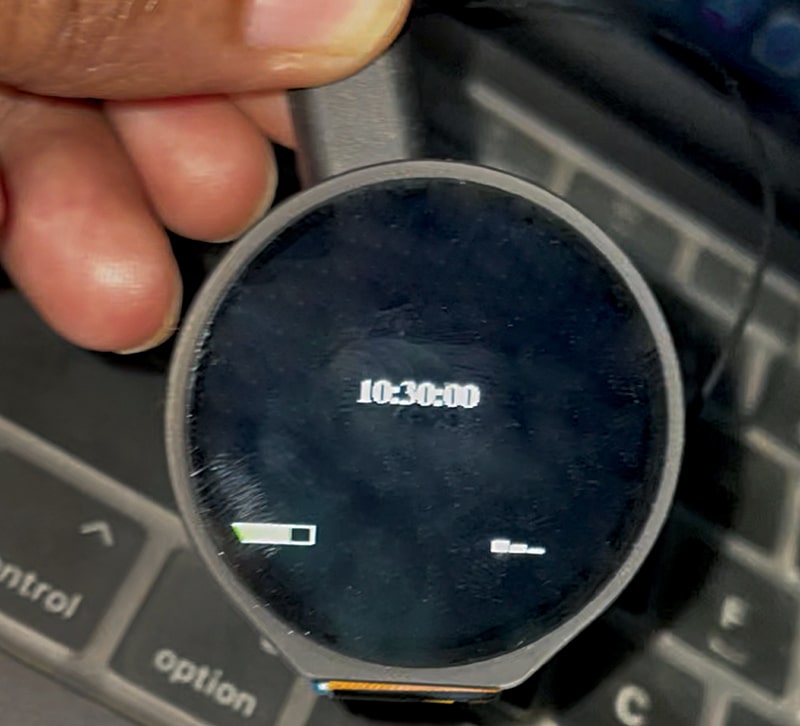
Integrating the calling system in Indus Phone
In the code, the GSM call library and the TFT_eSPI libraries combine into a single codebase. An idle screen is created to monitor incoming calls, battery status, and signal strength in a continuous loop. When a call comes in, the UI transitions to display the ‘attend’ and ‘end’ buttons. The function to attend the call is activated when the attend button is touched on the UI. The code checks the UI input; if the input is ‘attend’ or ‘end,’ it navigates to the corresponding screen and executes the appropriate function using the `call.answer();` and `call.hangup();` commands. Fig. 2 provides a code snippet for TFT_eSPI, while Fig. 3 depicts the initial idle screen code, which checks for incoming calls, network connectivity, and battery levels.
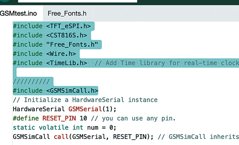
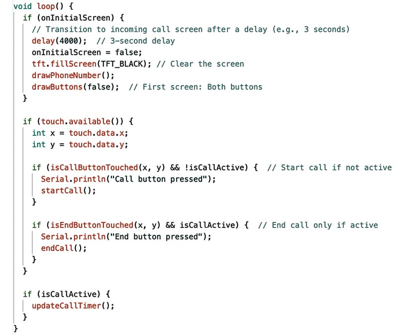
Fig. 4 presents the code snippet for verifying UI input and incorporating functionality for call attendance and hang-up based on touch input. Similarly, the UI for dialling numbers and making calls is seamlessly integrated. Fig. 5 showcases the Indusphone dial pad UI.
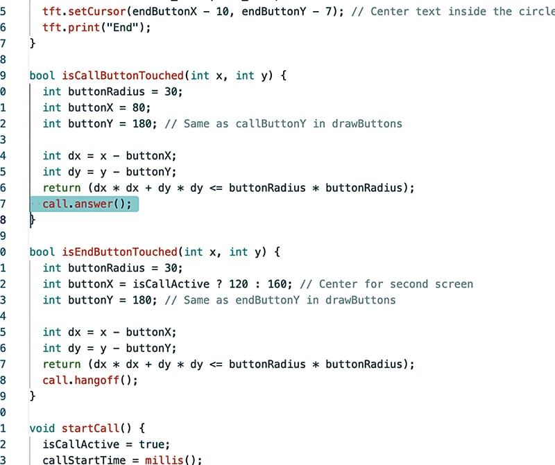
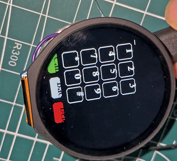
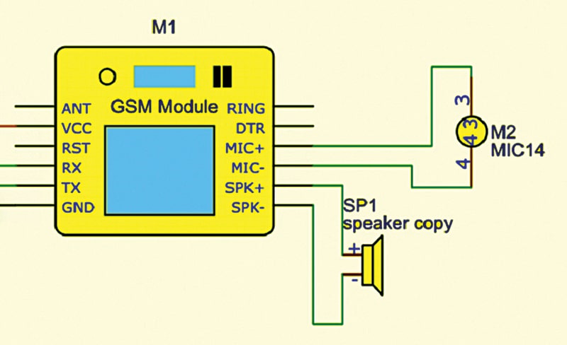
Fig. 6 illustrates the MIC and speaker connection with the GSM module. Once the function for attending or hanging up a call is initiated, the GSM module independently manages the receiver. If a number is dialled or a call is attended, the sound transmits through the small-sized SMD speaker linked to the GSM module, while voice input is captured from the SMD microphone. Refer to Fig. 6 for details.
Designing app
Next, the app is designed, incorporating basic features, such as contacts, phonebook, timer, games, and calculator. An additional UI screen named ‘App’ is created, along with sub-UIs for each feature. These invoke the necessary functions and execute the corresponding programs while monitoring incoming calls in the background through threading tasks.
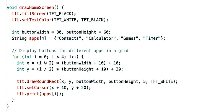
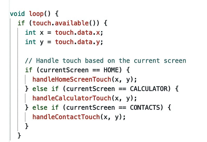
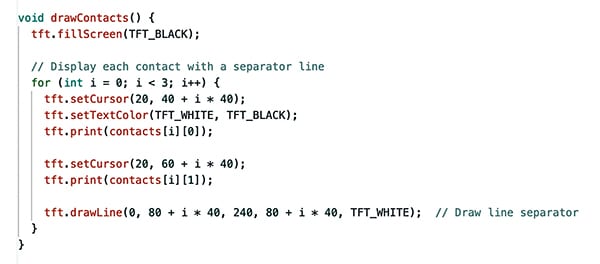
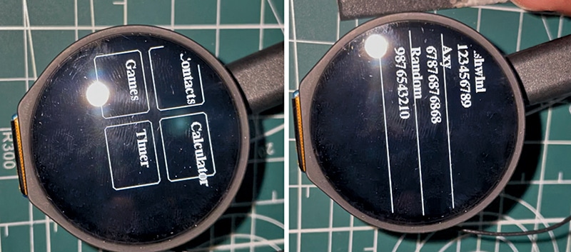
The App home screen displays a list of installed applications, allowing users to select the desired app via touch inputs from the touch panel. For contacts, selecting the relevant app triggers the internal command `AT+CPBR=1`, which retrieves and displays phone numbers and names on the screen. Similarly, selecting the calculator navigates to the next screen, invoking the calculator app. Fig. 7 shows the App home screen UI code, Fig. 8 presents the touch input code, and Fig. 9 displays the contacts code.
Designing calculator app
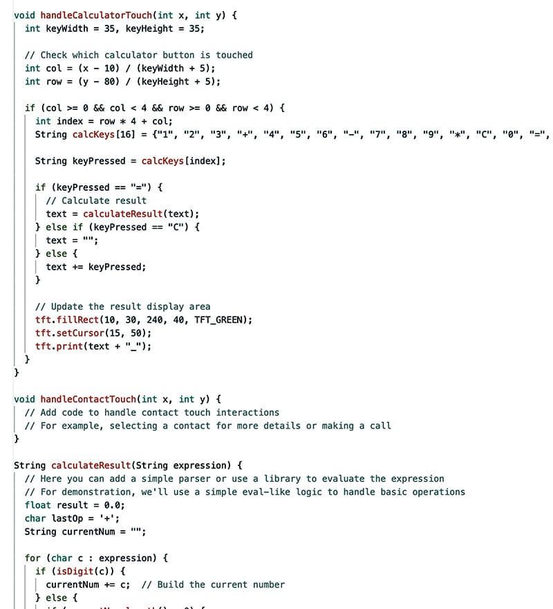
For the calculator app design, the same method as the display is employed. However, instead of using the `call.make` function, a custom function performs calculations based on user input and displays the results. The calculator UI features touch buttons for numerical and arithmetic function symbols. At the top of the screen, in green, the input and results of the calculations are presented. The code integrates two functions: one that handles touch input and another that displays the UI. The touch input handler activates UI actions in response to user input, while a separate function called `calculate` performs the calculations and displays the results on the phone screen. Fig. 11 presents the app calculator screen UI code.
EFY note. Further parts will be published in a coming issue, detailing upgrades to the phone with 4G LTE capabilities and additional functionalities.
Bonus. You can watch the video of the tutorial of this DIY project at https://www.electronicsforu.com/videos-slideshows/constructing-
indusphone-part-2
Ashwini Kumar Sinha, an IoT and AI enthusiast, is a Tech Journalist at EFY.


