The electronics circuit presented here serves as both an emergency light as well as an advertising display board. It relies on a 12-volt, 1.3Ah DC battery for power backup, ensuring more than two hours of illumination after a mains power outage.
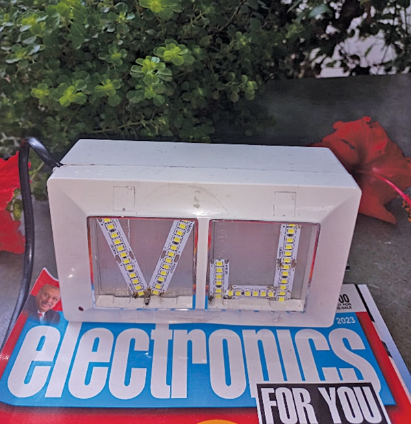
Fig. 1 displays the author’s fully assembled prototype of the emergency light cum advertising display board featuring the alphabets ‘V’ and ‘J.’
POC Video Tutorial In English
POC Video Tutorial In Hindi
| Parts List | |
| Semiconductors: | |
| IC1 | – LM7812, 12V voltage regulator |
| IC2 | – NE555 timer |
| T1 | – SL100 npn transistor |
| BR1 | – 1A bridge rectifier |
| D1-D2 | – 1N4007 rectifier diode |
| Resistors (all 1/4-watt, ±5% carbon): | |
| R1 | – 1-kilo-ohm |
| R2 | – 390-kilo-ohm |
| R3 | – 15-kilo-ohm |
| Capacitors: | |
| C1 | – 1000μF, 35V electrolytic |
| C2 | – 1μF, 35V electrolytic |
| C3 | – 100μF, 35V electrolytic |
| C4 | – 0.01μF, ceramic disk |
| Miscellaneous: | |
| Batt.1 | – 12V, 1.3Ah battery |
| S1 | – On/off switch |
| CON1-CON4 | – 2-pin connectors |
| RL1 | – 12V SPDT relay |
| X1 | – 230V AC primary to 15V, 1A secondary transformer |
| – 12V white LED strip (two) | |

Advertising Display Board – Circuit
The circuit diagram of the emergency light cum advertising display board is shown in Fig. 2.
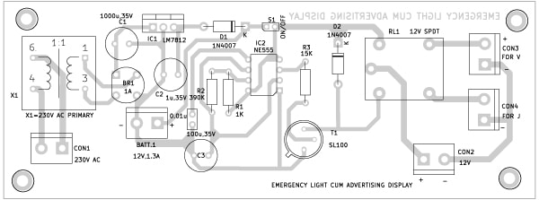
It comprises transformer X1, 12V voltage regulator LM7812 (IC1), timer IC NE555 (IC2), NPN transistor SL100 (T1), a 12V SPDT relay, and some other components.
The transformer and bridge rectifier recharge the battery directly when the mains 230V AC is connected across CON1.

In this circuit, the timer IC NE555 is configured in free-running multivibrator mode with its on and off period set at about 25 seconds. The pulse generated by timer IC NE555 at its pin 3 is fed to the base of NPN transistor SL100 via resistor R3.
This pulse signal causes the transistor to start conducting, thereby energizing the relay. Due to the magnetic properties of the relay, it attracts the attached plunger. As a result, the relay switches from normally open (N/O) mode to normally closed (N/C) mode.
In both N/O and N/C modes of the relay, the LED strip available in the market, arranged in the form of alphabets ‘V’ and ‘J,’ also illuminates the nearby area.
After switch S1 is turned on, the first LED strip (alphabet ‘V’) lights up. After 25 seconds, the other LED strip (alphabet ‘J’) lights up.
At this time, however, the LED strip alphabet that was previously illuminated automatically turns off.
This alternating on-and-off operation not only extends the life of the LED strips but also saves electrical power.
Also Check: Inverter Bulb for Emergency
PCB Design
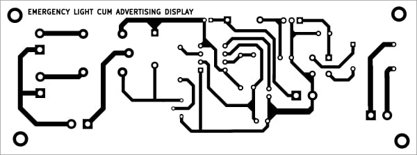
An actual-size, single-side PCB layout for the circuit is shown in Fig. 3 and its component layout is shown in Fig. 4.


Assembly and Testing
After assembling the circuit on the PCB, enclose it in a suitable box. The box used by the author is a PVC electrical board available in the market at a low cost.
Fix the alphabets ‘V’ and ‘J,’ made with LED strips, across CON3 and CON4, respectively, on the front of the box.
Connect switch S1 on the front side of the cabinet to switch on/off the display. Instead of ‘V’ and ‘J,’ you can use any other alphabets or short words for advertisements.
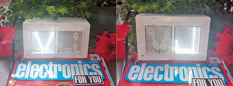
The prototype shown in Fig. 5 demonstrates the alternating display of ‘V’ and ‘J.’

Once the circuit is assembled, install the unit at a suitable place at the gate of an office/residence.
If you wish to use it as an emergency light only, omit the letters/words and arrange the strips in straight lines or any other pattern of your choice, solely for lighting. Now, the circuit is ready to use.


